June 24, 2026
MIT Gleanmer Edge AI Chip: Practical Guide to 3D Mapping
MIT Gleanmer Edge AI Chip guide for production teams: compare workflow fit, risk, cost, review burden, and deployment guardrails before shipping safely.
Article focus
The MIT Gleanmer edge AI chip is a research system-on-chip for low-power, on-device 3D Gaussian mapping. For robotics, AR, and edge AI teams, the practical question is not whether Gleanmer is exciting.
Section guide
The MIT Gleanmer edge AI chip is a research system-on-chip for low-power, on-device 3D Gaussian mapping. For robotics, AR, and edge AI teams, the practical question is not whether Gleanmer is exciting. It is what this design says about moving real-time spatial awareness closer to small devices that cannot afford large batteries, large memory, or round-trip cloud inference.
At Van Data Team, we start by mapping the workflow before choosing the stack: sensor input, local decision loop, telemetry capture, human review, and reporting. That is the right lens for Gleanmer. The chip is not a general-purpose AI platform or a product we can assume teams can buy today. It is a useful technical signal: edge perception becomes more practical when the mapping representation, memory pattern, and hardware are designed together. For teams evaluating similar systems, our AI and data engineering services usually turn that signal into an operational plan: what runs on-device, what gets logged, what gets reviewed, and what belongs in cloud analytics.
How Van Data Team Makes This Operational
At Van Data Team, we treat MIT Gleanmer edge AI chip as an operating workflow, not a theory section. We start by mapping the current handoff, source systems, decisions, review gates, dashboards, and recovery paths. The useful output is a scoped delivery plan: which signals to collect, which workflow gaps to close, which automation belongs behind a human review gate, and which dashboard or runbook lets the team act next.
Key Takeaways
- Gleanmer is an MIT research SoC for real-time 3D Gaussian occupancy mapping, aimed at constrained edge uses such as tiny robots and AR devices.
- The core shift is representational: flexible Gaussian ellipsoids can describe obstacles and free space more compactly than voxel-heavy maps.
- MIT News reports about 6 milliwatts of power use and says the chip required only about 2.5 percent of the power used by the best existing chip for map construction.
- Production teams should treat Gleanmer as an edge AI design pattern, not as a ready commercial deployment path unless availability is separately confirmed.
- The evaluation work should cover power, memory, latency, map quality, collision avoidance, observability, failure recovery, and the review burden around safety-critical behavior.
What Is the MIT Gleanmer Edge AI Chip?
Gleanmer is a system-on-chip developed by MIT researchers for energy-efficient, on-device 3D Gaussian occupancy mapping. According to MIT News, it helps small autonomous robots and battery-limited devices build real-time 3D maps using about as much power as a single LED.
The important phrase is "system-on-chip." Gleanmer is not just a mapping algorithm and not just a generic AI accelerator. It combines an efficient mapping algorithm with dedicated hardware designed around that workload. The related arXiv preprint describes Gleanmer as a 6 mW SoC for real-time 3D Gaussian occupancy mapping, with a GMMap accelerator and algorithm-hardware co-optimizations.
In plain terms, the chip helps a device understand surrounding space without carrying a heavy compute budget. Instead of building a 3D map from many rigid cube-like cells, called voxels, it uses Gaussian ellipsoids. These ellipsoids can stretch, narrow, and fit curved geometry more efficiently.
That matters because a tiny robot navigating a pipe, duct, shelf aisle, or cluttered indoor path has no room for waste. It needs a map that is detailed enough for collision avoidance, compact enough for local memory, and fresh enough for real-time movement. Gleanmer addresses that pressure by reducing how much raw depth data must be stored and revisited.
What it is not: Gleanmer should not be framed as a cloud robotics platform, a general LLM accelerator, or a commercial robotics product unless new source material confirms that. The strongest current reading is research-focused: a fabricated chip and architecture that show how edge mapping can be made much more efficient.
Why This Matters for Tiny Robots and Edge AI
Small edge devices face a practical constraint stack. They need to sense the world, update a map, plan a path, and recover from uncertainty, all under a tight power and memory budget. That is different from a server-side AI workflow where compute can be scaled horizontally and logs can be stored cheaply for later inspection.
MIT's public writeup says Gleanmer generated real-time 3D maps while consuming about 6 milliwatts, and required only about 2.5 percent of the power used by the best existing chip for map construction. In the same article, MIT says the chip lets a robot chart a safe trajectory using about 20 percent of the energy it would otherwise need by reusing compact Gaussians during planning.
Those figures are useful, but the operating lesson is broader than the number. Edge AI teams should ask: where is energy actually being spent? Often it is not only the model or mapping math. It is memory movement, repeated passes over raw data, and storing representations that are too large for the device.
A hypothetical example makes this concrete. A small inspection robot moving through an industrial HVAC route cannot assume stable wireless connectivity or continuous cloud processing. If the robot must pause, upload frames, wait for a map update, and then move again, navigation becomes fragile. If it can update a compact local map and send selected debug signals upstream, the system can remain useful even when connectivity is poor.
This is also where architecture affects cost. Moving perception work to the edge may reduce cloud inference and transfer pressure, but it adds new requirements for device telemetry, fleet monitoring, and test coverage. Teams already building real-time pipelines with Kafka will recognize the pattern: the sensor loop and the observability loop are separate, but both need disciplined design.
How Gleanmer Works at a High Level
The following illustration summarizes depth data to edge navigation:
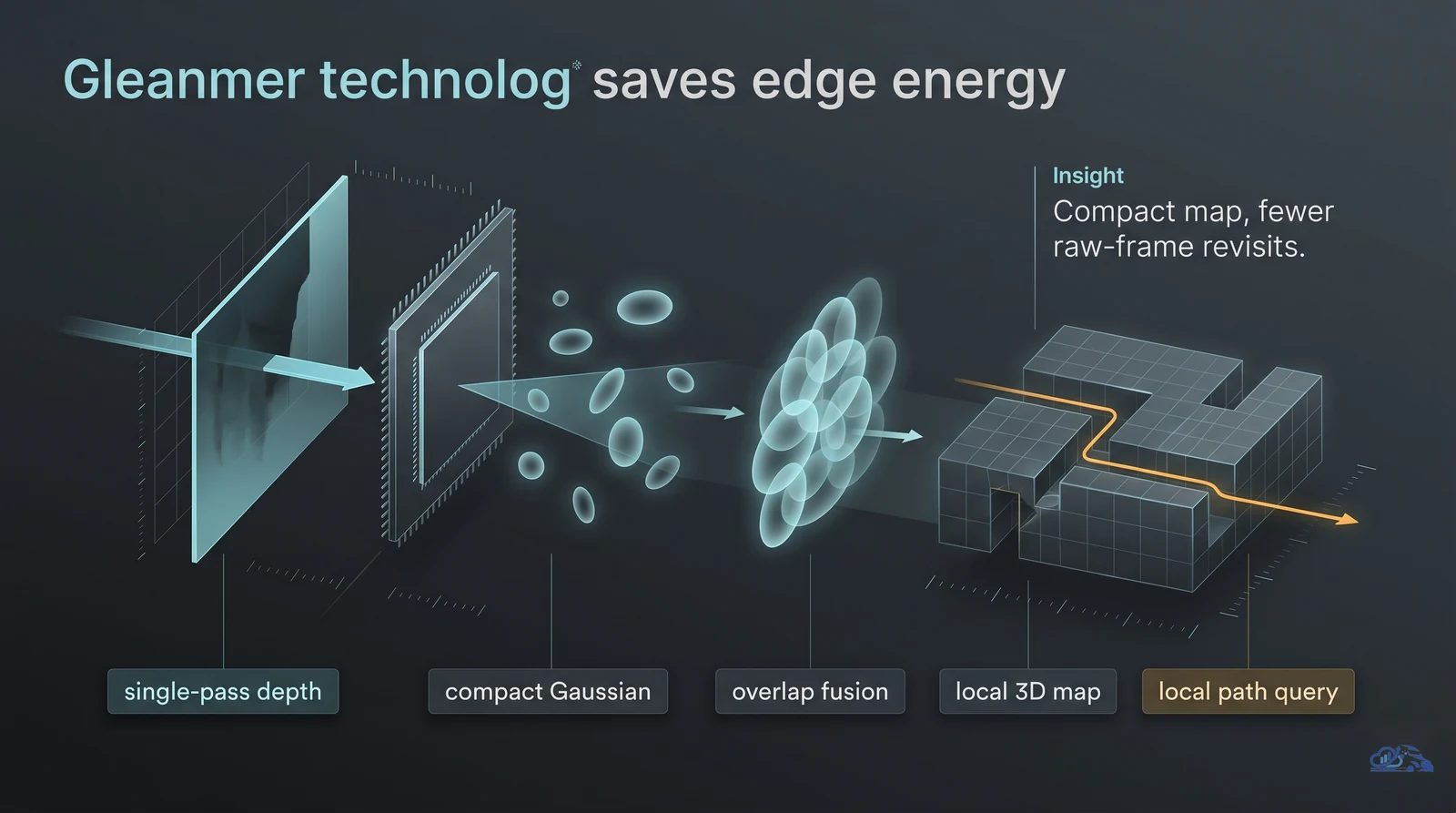
The Gleanmer workflow can be understood as four steps: take in depth data, create compact Gaussian map elements, fuse overlapping elements, then query the map for navigation.
From Depth Image to 3D Map
A depth image tells the system how far visible surfaces are from the sensor. Traditional mapping approaches may need to load and process those images multiple times. MIT describes Gleanmer differently: it generates Gaussians from depth images with one pass, then discards the images so the chip does not need to store an entire image at once.
That is a hardware-friendly design. Less raw data retained means less memory pressure. Less memory movement usually means less energy consumption. The workflow is shaped around what the chip can do efficiently, not around an abstract algorithm that later has to be forced onto constrained hardware.
Neighbor Comparisons Instead of Broad Matching
MIT's explanation says Gleanmer avoids comparing every pixel with every other pixel. It assumes nearby pixels often belong in the same Gaussian, so it compares pixels only to their neighbors.
That assumption is not just a mathematical detail. It is a production tradeoff. Local comparisons reduce compute and memory load, but teams still need to validate where the assumption holds. Smooth walls, pipes, corners, and furniture may behave differently from reflective surfaces, moving objects, or sensor-noisy scenes.
Gaussian Ellipsoids Instead of Voxels
Voxel maps divide space into small cubes. They are intuitive and widely used, but they can become memory-heavy when a scene needs fine detail. Gaussian ellipsoids are more flexible. One elongated ellipsoid can represent a region that might otherwise require many small voxels.
| Mapping pattern | Practical strength | Practical limitation | Edge implication |
|---|---|---|---|
| Voxel-style map | Simple spatial grid, straightforward occupancy reasoning | Can require many cells to represent curved or elongated shapes | Higher memory pressure on small devices |
| Gaussian ellipsoid map | Compact representation for surfaces, obstacles, and free space | Requires careful validation of approximation quality | Better fit for constrained memory and power budgets |
| Cloud-built map | More compute and storage available | Depends on connectivity and round-trip latency | Useful for analytics, less reliable for immediate navigation |
| On-device compact map | Local, fast decision support | Harder debugging and stricter hardware limits | Better fit for safety-critical local reactions |
Direct Fusion of Overlapping Gaussians
As a robot moves, it sees the same object from different viewpoints. That can create overlapping map elements. MIT says the researchers developed a method to fuse overlapping Gaussians directly, without revisiting the original raw pixels.
This is the design move that production teams should notice. The system keeps computation close to the compact representation. It does not depend on returning to bulky raw frames every time the map changes. For edge systems, that pattern can be as important as the mapping technique itself.
Implementation Lessons for Production Teams
The mistake we see is treating edge AI as a model selection problem. In constrained systems, the model is only one part of the loop. The workflow includes sensors, memory, local processing, path planning, telemetry, exception handling, and post-run review.
A Gleanmer-like architecture suggests this implementation pattern:
- Define the physical constraint budget: power, memory, thermal envelope, sensor rate, and acceptable decision latency.
- Choose a representation that fits that budget, not the most expressive representation available.
- Minimize raw-data revisiting inside the local loop.
- Send telemetry and selected debug artifacts upstream for monitoring, not for every immediate navigation decision.
- Use simulation, test scenes, and safety review before trusting physical movement.
For a robotics or AR team, the surrounding architecture might look like this in prose: the device captures depth input, updates a compact local map, performs navigation or spatial reasoning locally, emits summarized telemetry, and stores selected failure snapshots for later review. The cloud side receives signals, tracks drift, compares runs, and produces operational reports. If an AI agent is used to summarize incidents, its token budget belongs in that diagnostic workflow, not in the device's real-time control loop.
That distinction matters. At Van Data Team, we would not start by asking which chip or model is fashionable. We would start with the signal map: which signals are needed for safe local action, which are needed for debugging, which are needed for dashboards, and which should trigger human review. From there, agentic BI and reporting can help turn field telemetry into explainable dashboards, while AI agent development can support review workflows with guardrails and escalation paths.
A practical implementation scope should produce clear artifacts: a device-to-cloud signal map, validation scenes, telemetry schema, latency and power test plan, failure-mode register, and dashboard gap review. Without those, an edge AI prototype may look impressive while remaining hard to operate.
Best Practices for Evaluating Gleanmer-Like Systems
Use Gleanmer as a framework for asking better questions about edge AI mapping systems. The best practices below apply whether the implementation uses Gaussian occupancy mapping, a voxel map, a learned perception model, or a hybrid approach.
Start With the Constraint Budget
Before testing algorithms, write down the physical limits. The device budget should include power, memory, compute, sensor input rate, storage, thermal behavior, and navigation latency. If those numbers are missing, the evaluation will drift into demo thinking.
The budget also has a review side. How much data can the device log? How much can the cloud ingest? Who reviews anomalies? What is the recovery path when perception is uncertain? If the system controls motion, the failure review is part of the product, not a compliance afterthought.
Validate the Representation
Compact maps are useful because they discard or compress information. That also means teams must test what gets lost.
For Gaussian-style maps, ask:
- Which obstacle shapes are represented well?
- Which surfaces create noisy or unstable map elements?
- How does the map behave when objects move?
- What happens when sensor input is incomplete?
- Can the system distinguish free space from unknown space clearly enough for path planning?
The right answer is not always "more detail." The right answer is enough reliable detail for the task, at a power and memory cost the device can sustain.
Test the Full Navigation Loop
Do not validate the mapper alone. Test the complete loop: depth input, map update, path planning, collision avoidance, recovery, telemetry, and review. A map that looks good offline may still fail when the device must act continuously.
A practical test matrix can be simple:
| Evaluation area | What to test | Failure signal |
|---|---|---|
| Power and thermal behavior | Sustained mapping under realistic movement | Device throttles, resets, or drains too quickly |
| Map quality | Obstacles, free space, corners, curves, clutter | False free space or unstable obstacle boundaries |
| Navigation behavior | Path planning under uncertainty | Late turns, oscillation, unsafe route choice |
| Observability | Telemetry and debug capture | Incidents cannot be reconstructed |
| Recovery | Sensor noise, blocked path, lost localization | No safe stop or escalation behavior |
For teams deciding whether edge processing also changes infrastructure spend, a cloud cost optimization review can compare local inference, onboard compute, cloud analytics, and data transfer tradeoffs without pretending that edge processing makes cloud costs disappear.
Common Mistakes to Avoid
The first mistake is calling Gleanmer a general AI chip. Its value is specific: efficient 3D Gaussian occupancy mapping for edge-based applications. That specificity is why the research is interesting.
The second mistake is treating the MIT power figures as a blanket benchmark for every robotics workload. MIT News reports the 6 mW result and the power comparison for map construction, but production teams still need to measure their own sensors, movement patterns, environments, and safety requirements.
The third mistake is ignoring commercial status. The supplied sources describe research, a preprint, and a public MIT announcement. They do not establish that a team can buy Gleanmer, integrate it into a fleet, or receive vendor support.
The fourth mistake is forgetting observability. Edge systems fail in physical context. If the only artifact after an incident is "the robot stopped," the engineering team cannot improve the workflow. Capture enough telemetry to reconstruct the decision loop without overwhelming storage or network budgets.
The fifth mistake is pushing every hard decision into an AI agent. Agents can help summarize logs, route exceptions, and prepare review packets. They should not be used to paper over unclear safety rules, missing telemetry, or unvalidated path planning.
A useful CTA at this stage is concrete: if your team is evaluating edge perception, Van Data Team can produce a scoped workflow review with a signal map, telemetry plan, dashboard gap review, and implementation risk register through our founder-led delivery model. That gives engineering, data, and operations teams a shared operating document before hardware choices become expensive.
Conclusion
The MIT Gleanmer edge AI chip matters because it shows how real-time 3D mapping can move closer to the smallest edge devices. The technical shift is not a single trick. It is the combination of compact Gaussian representation, single-pass depth processing, neighbor-based comparisons, direct fusion, and hardware designed around the workload.
For operators, the practical takeaway is disciplined evaluation. Do not ask only whether an edge AI system can produce a map. Ask what it costs in power, memory, latency, review burden, observability, and recovery behavior. Then test the full loop before trusting it in physical movement.
For teams exploring production AI, robotics telemetry, AR workflows, or edge-to-cloud architecture, the right next step is a scoped implementation review: define the constraint budget, signal map, validation scenes, monitoring dashboard, and failure recovery path. That is how promising research turns into systems a team can actually operate.
Article FAQ
Questions readers usually ask next.
These short answers clarify the practical follow-up questions that often come after the main article.
Gleanmer is an MIT research system-on-chip for real-time 3D Gaussian occupancy mapping. It is designed to help constrained edge devices, including tiny robots and AR devices, build compact 3D maps locally.
MIT News reports that Gleanmer consumes about 6 milliwatts of power while generating detailed 3D maps in real time. The same article describes that as about as much power as a single LED.
Voxel mapping represents space with cube-like 3D pixels. Gleanmer uses Gaussian ellipsoids, which can adapt their size, shape, and thickness to represent geometry more compactly. That compactness helps reduce memory and power pressure.
The supplied MIT sources mention small autonomous robots, battery-limited devices, and lightweight AR headsets. The broader lesson applies to edge AI systems where local mapping, limited power, and low latency matter, but unsupported use cases should be validated separately.
The current public sources describe MIT research and a technical preprint, not commercial availability. Production teams should treat Gleanmer as a reference architecture and evaluation signal unless new official availability or licensing information confirms a deployment path.
Use it to pressure-test your edge AI architecture. Ask whether your representation is compact enough, whether raw data is revisited too often, whether navigation can run locally, and whether telemetry supports incident review and recovery.
Need a similar system?
If this article maps to a workflow your team already operates, the next step is usually a scoped review of the system, constraints, and rollout path.
Free edge review
Scope Edge 3D Mapping Readiness
Review MIT Gleanmer edge AI chip implications and leave with a practical plan for latency, memory, logging, and human review.
- On-device vs cloud decision map for 3D mapping workloads
- Latency, memory, and power assumptions to test before adoption
- Telemetry checklist for small robot navigation and recovery
- Human review gates for safety-critical edge decisions
Related articles
View all
Claude Fable 5 vs GPT 5.5 vs Gemini 3.5 Flash Thinking

Claude Fable 5: A Practical Guide for Production AI Workflows

Optimizing Docker Image Build Times: A Practical Guide for Production Teams
